(Support door to door service)Order(MOQ):
1Product Origin:
ChinaLead Time:
10DaysShipping Port:
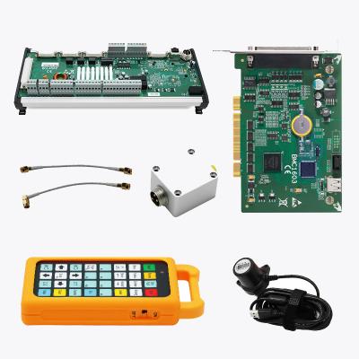
QingdaoJCZ LMCV4 Fiber / Co2 Laser Marking Control Card

Features
1. Use the DB25 socket connector, Can be directly connected pulsed fiber laser.
2. The galvanometer control signal is digital and can be directly connected to a universal digital galvanometer.
3. Extended axis (stepper motor/servo motor) output: It can output the direction/pulse signal of two channels to control the stepper motor (or servo motor), which can be used for shaft rotation or splicing.
4. 6 universal input digital signals (TTL compatible). XORG0 (IN14) (IN15) where IN0~IN3 are designated as laser state input signals are quoted by CON2 (Laser ST0~Laser ST3).
5. 2 general purpose output digital signals (TTL compatible). OUT4, OUT5 are TTL outputs;
6. ReMark (cache content repeated marking) Signal: used for marking the same content, requiring high-speed marking.
7. Compatible with USB2.0.
Specifications
| Model | LMCV4-FIBER-MM | LMCV4-DIGIT-M |
| Connect Method | USB2.0 |
|
| Laser Signal | Output laser control signal with DB25 socket |
Laser (high/low level), Analog Power (PWM+/PWM-/PWMTTL), Analog Frequency |
| Number of Input Ports | 2-way universal input port (TTL) |
|
| Number of Output Ports | 2-way universal output port (TTL) |
|
| Remark Signal |
Cache content repeated engraving |
|
| Extended Axis | Support 1 way extension axis |
|
| Flight marking | Not support |
|
| Multi-head Carving | Not support |
|
| Software Secondary Development | Not support |
|
| Suitable Laser | Fiber Laser |
CO2 /YAG/UV Laser |
| Applicable Material | Metal black photosensitive material |
Glass, Plastic, Wood, Rubber, Paper |
| Support Operating System | XP WIN7 WIN8 WIN10 32/64 Bit system | |
| Built-in Encryption chip | No External Dongle Required |
|
|
Power supply |
5V 3A |
|
Dimension
Unit: mm

Interface Definition
LMCV4-FIBER

| CON1: DB15 Galvanometer Control |
||||
| Pin NO. |
Name |
Description |
||
| 1, 9 |
CLK-/CLK+ |
Clock signal ± |
||
| 2, 10 |
SYNC-/SYNC+ |
Sync signal ± |
||
| 3, 11 |
XChannel-/XChannel+ |
Galvanometer X signal ± |
||
| 4, 12 |
Y Channel- /YChannel + |
GalvanometerY signal ± |
||
| 5, 13 |
NULL |
Reserved |
||
| 6, 14 |
NULL |
Reserved |
||
| 7 |
NULL |
Reserved |
||
| 8, 15 |
GND |
Ground |
||
| CON2: DB25 Laser Control |
||||
| Pin NO. |
Name |
Description |
||
| 1 |
XORG0 |
The home signal of extension axis X. To use this pin just connect it and GND to a switch. In software In14 represents this pin. |
||
| 2 |
GIN15 |
General input in15. using GND as a reference ground |
||
| 2, 10 |
Out4, Out5 |
General Output Out 4-0ut 5. using GND as reference ground. They are all TTL output |
||
| 4, 5 |
Vin |
Input pin for 5v power supply. |
||
| 11, 12,13 |
GND |
Reference ground of 5V power supply |
||
| 14 |
XDIR+ |
Direction signal of extension axis X. lt is a TTL output. For common anode, use VCC and XDlR+ signals, and VCC is anode signal. |
||
| 15 |
XPUL+- |
Pulse signal of extension axis X. lt is a TTL output. For common anode. use VCC and XDlR+ signals, and VCC is anode signal. |
||
| 8 |
ReMark |
Repeat marking signal. Use GND as a reference ground, to use thissignal just connect a switch between this pin and GND. When it is activated the control will mark the content in the cache. |
||
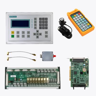
Package List


Industrial Park Weiji Town,Xuzhou City,Jiangsu Province, China
Copyright © 2024 Anhui Codos Laser Technology Development Co., Ltd. All Rights Reserved.
Sitemap | Blog | Xml | Privacy Policy 


 русский
 español
 العربية